Servos wiring diagrams are used to connect the different components of a servo system together. They provide a visual representation of how the servo motor and other parts of the system interact. This can be useful for troubleshooting and understanding the overall system design.
A servo wiring diagram is made up of two main parts: the power supply and the signal lines. The power supply provides power to the servo motor, allowing it to operate. The signal lines then allow for the exchange of information between the motor and the other components in the system. This can include things like the control board, encoders, sensors, and other parts.
Understanding the servos wiring diagram is important to ensure that the system is functioning correctly. It is also important to make sure that all the components are properly connected and that they are in the correct order. If any part of the system is not connected correctly, it could cause the servo motor to malfunction or stop working altogether. Additionally, if the wiring diagram is incorrect or incomplete, it could lead to problems with the data being sent to and from the servo motor. To avoid any issues, it is essential to follow the wiring diagram closely.
Servos wiring diagrams can be a great tool for understanding the inner workings of servos systems. By giving a clear picture of how the components interact, it can help troubleshoot potential problems and ensure that the system is functioning properly. Additionally, it can be used to gain a better understanding of the overall design of the system and how its components are connected. With the help of a servos wiring diagram, anyone can gain an understanding of the inner workings of a servo system.

Connect The Servos To Boe Shield Learn Parallax Com

How Servo Motor Works Interface It With Arduino Last Minute Engineers

How To Controll A Servo With 5 Wires Motors Mechanics Power And Cnc Arduino Forum

Wiring Diagram Of Drive Weihong Doc

Servomechanism Wiring Diagram Radio Receiver Electrical Wires Cable Png 2060x1300px Servo Communication Control System

Connection Diagram Reference Specifications Of Servo Amplifier Faldic α Fuji Electric Global

Wiring Diagram Weihong Doc

Controlling Servo Motor Setting Angle Using Arduino Ide Stempedia

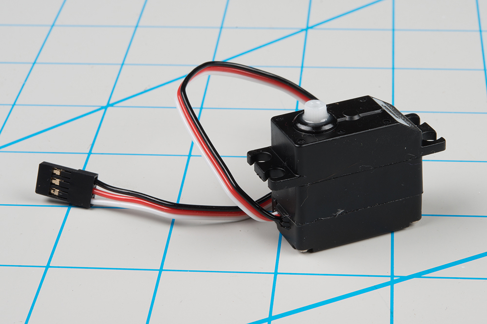
Hobby Servo Tutorial Learn Sparkfun Com

Servo Motor Basics With Arduino Doentation

Physci 70 Introduction To Digital Fabrication

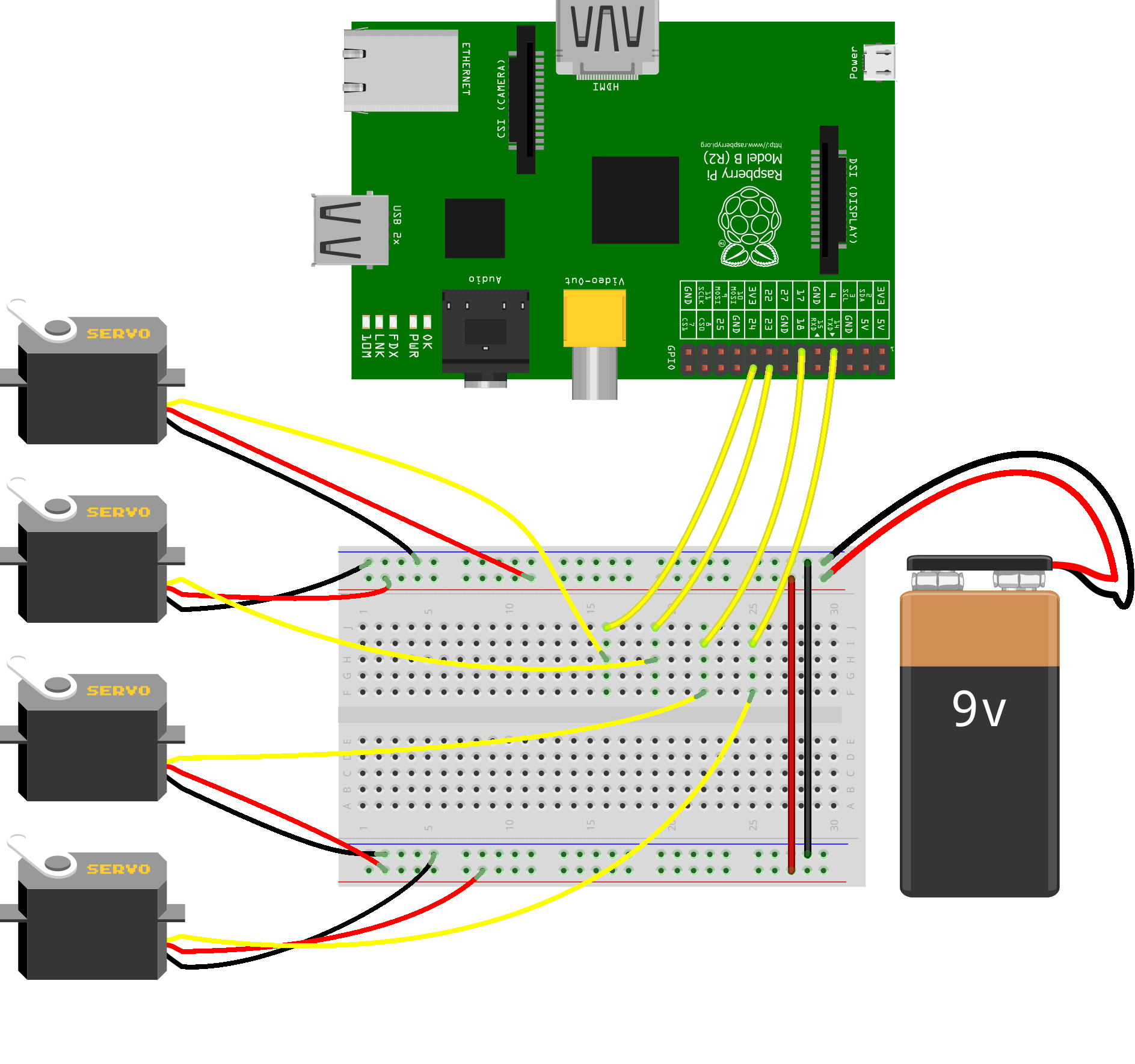
How To Use Servos On The Raspberry Pi Circuit Basics

Hobby Servo Tutorial Learn Sparkfun Com

How To Control Servo Motors With Arduino Complete Guide

Schematic Representation Of The Wiring Diagram Depicting Control Scientific

Wiring Diagram Weihong Doc

Servo Motor Control Schematic Pyroelectro News Projects Tutorials

Servo Motor Controller Or Driver Electrical4u

Hobby Servo Tutorial Learn Sparkfun Com

Esp32 Potentiometer Triggers Servo Motor Tutorial