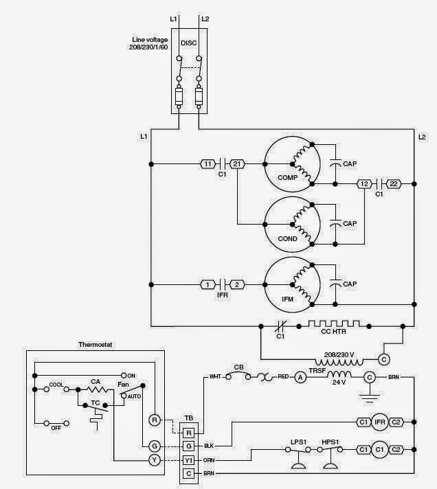
HVAC wiring diagrams 101: Understanding the Basics
HVAC wiring diagrams are essential for anyone who is installing, repairing, or maintaining heating, ventilation, and air conditioning (HVAC) systems. Understanding these diagrams can help ensure that a professional installation is completed correctly, without any safety risks. With a better understanding of HVAC wiring diagrams, you can avoid costly mistakes and make sure your HVAC system is running as efficiently as possible.
The first thing to understand about HVAC wiring diagrams is that there are several different types. Each type is suited for a specific purpose, such as controlling fan speed, controlling temperature, or providing power to components. The type of diagram used will depend on the model and type of system being installed or repaired. Knowing which type of diagram to use can save time and effort when troubleshooting an HVAC system.
When reading an HVAC wiring diagram, it's important to pay attention to the symbols used. They provide crucial information about the components of the system, such as the voltage and current levels, as well as the size and type of wires that connect the various components. Additionally, the diagrams may contain notes about the installation process, such as the order in which components should be connected. Paying close attention to these details can help you properly install an HVAC system and avoid any costly mistakes.
Finally, it's essential to follow all local codes and regulations when working with HVAC wiring diagrams. This includes making sure that all electrical components are up to code and that the wiring is properly insulated. Following all safety regulations can help protect you, your property, and your family.
HVAC wiring diagrams can seem intimidating, but with a little knowledge, they can be easy to understand. Once you understand the basics, you can make sure that your HVAC system is installed correctly and efficiently.

All About Definite Purpose Contactors Wolf Automation

Chromalox Thermostat Wiring Diagrams For Hvac Systems Installation Instructions

Aaon All Products Pages 101 144 Flip Pdf Fliphtml5
Wiring Diagram

Figure 40 Wiring Diagram For General Electric Ordnance No 7355925 150 Amper Generator Control Box Complete Hook Up To Vehicle Electrical System
Mr 100 200 Series

Trailer Wiring 101

Manuals Air Conditioners Boiler Furnace Heat Pump Free S

2013 Nissan Altima Repair Manual Heater Air Conditioning Control System Section Hac Page 34 Pdf

Nissan Maxima Service And Repair Manual Wiring Diagram Heater Air Conditioning Control System

24ana7 2w Revefrsing Compressor Manualzz
Hvac Talk Heating Air Refrigeration Discussion

Schematic Diagrams For Hvac Systems Modernize

Gm Full Size Trucks 1988 1998 Wiring Diagrams Repair Guide Autozone

Er Resistor Electrical Diagram Car How To

How To Read Ac Schematics And Diagrams Basics Hvac School

Wiring Diagrams Carrier

Trailer Wiring 101