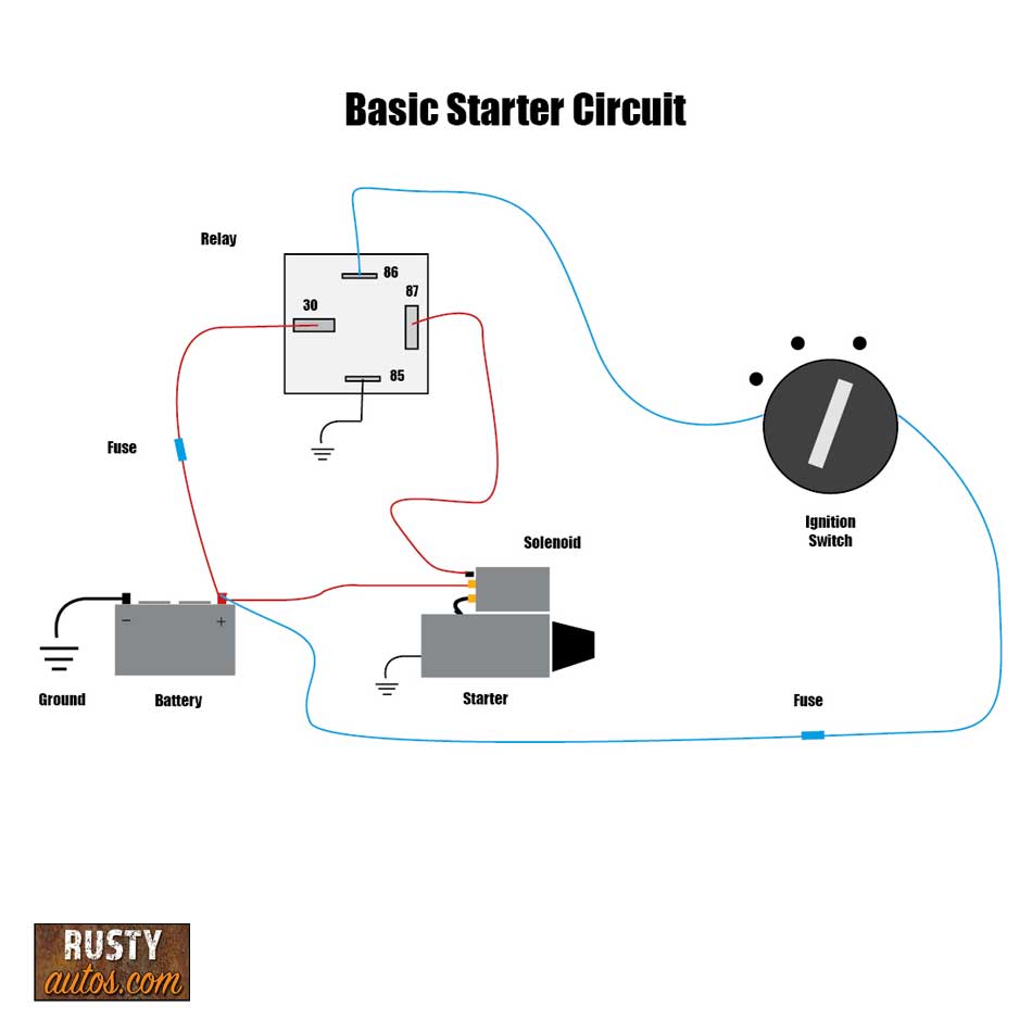
Circuit and wiring diagrams are essential tools for any electrical technician or engineer. These diagrams provide a visual representation of the components, connections, and operations of an electrical circuit. They help in troubleshooting, diagnosing, and installing electrical systems.
Circuit diagrams usually consist of schematics, line diagrams, symbols, and other graphical elements. Schematics show how components are connected together in a logical manner. Line diagrams are used to show the physical relationship between components. Symbols are used to represent components and connections in the circuit.
Wiring diagrams, on the other hand, provide more details about the connections and physical layout of the components. Wiring diagrams often include a legend that explains the meaning of the symbols used. They also show the location of components and connections in the circuit. Wiring diagrams are used to install and maintain electrical systems, as well as to troubleshoot and diagnose issues with existing systems.
The use of circuit and wiring diagrams can greatly reduce the time and effort needed to complete a project. By using these diagrams, technicians and engineers can quickly identify and solve problems related to electrical systems. It is important to be aware of the differences between circuit and wiring diagrams, as they are both important tools for understanding and maintaining electrical systems.

Developing A Wiring Diagram Circuit 3

Bmw Wiring Diagram Electrical Wires Cable Circuit Png 960x1242px Area Artwork Black And

Circuit Diagram And Its Components Explanation With Symbols

How To Read Electrical Schematics Circuit Basics

Electrical Panel Wiring Diagram

How To Read An Electrical Wiring Diagram Inst Tools

Ladder Diagram Schematic Wiring Electrical Academia

Wiring Diagrams

Circuit Breaker Wiring Diagrams Web Dc Power Supply Wire Up A 12v Transpa Png 640x483 Free On Nicepng

Resources

Developing A Wiring Diagram Circuit 1

Circuit Breaker Control Schematic Explained
What Is The Difference Between An Electrical Schematic Diagram And A Circuit Quora

How To Read A Schematic Learn Sparkfun Com

Wiring Diagram Everything You Need To Know About

Figure 11 Wiring Diagram Of A Car S Electrical Circuit

How To Construct Wiring Diagrams Controls

How To Read Car Wiring Diagrams Short Beginners Version Rustyautos Com

Electrical Network Wiring Diagram Wires Cable Circuit Wall Creative Angle Plan Png Pngwing